Thursday, July 26, 2018

https://maker.pro/arduino/projects/build-arduino-self-balancing-robot/

How to use an Arduino to build a robot that balances itself like a Segway.
arduino-self-balancing-robot-1-813x1024.jpg
Ever wonder how Segways work? This tutorial will show you how to build an Arduino robot that balances itself — just like a Segway!

How Does Balancing Work?

To keep the robot balanced, the motors must counteract the robot falling. This action requires feedback and correcting elements. The feedback element is the MPU6050 gyroscope + accelerometer, which gives both acceleration and rotation in all three axes (MPU6050 I2C basics). The Arduino uses this to know the current orientation of the robot. The correcting element is the motor and wheel combination.
DIY_AMBOT_images.jpg

Connection Diagram

AmBOT_bb-908x1024.jpg
Complete Fritzing diagram
Connect the MPU6050 to the Arduino first and test the connection using the codes in this IMU interfacing tutorial. If data is now displayed on the serial monitor, you're good to go! Proceed to connect the rest of the components as shown above. The L298N module can provide the +5V needed by the Arduino as long as its input voltage is +7V or greater. However, I chose to have separate power sources for the motor and the circuit for isolation. Note that if you are planning to use a supply voltage of more than +12V for the L298N module, you need to remove the jumper just above the +12V input.

Building the Robot

arduino-self-balancing-robot-2-842x1024.jpg
Robot frame (made mostly of acrylic slab) with two geared DC motors
arduino-self-balancing-robot-4.jpg
Main circuit board, consisting of an Arduino Nano and MPU6050
l298n-motor-driver.jpg
L298N motor driver module
dc-geared-motor-wheels.jpg
Geared DC motor with wheel
The self-balancing robot is essentially an inverted pendulum. It can be balanced better if the center of mass is higher relative to the wheel axles. A higher center of mass means a higher mass moment of inertia, which corresponds to lower angular acceleration (slower fall). This is why I've placed the battery pack on top. The height of the robot, however, was chosen based on the availability of materials.
arduino-self-balancing-robot-3-225x300.jpg
Completed self-balancing robot. At the top are six Ni-Cd batteries for powering the circuit board. In between the motors is a 9V battery for the motor driver.

More Self-balancing Theories

In control theory, keeping some variable (in this case, the position of the robot) steady needs a special controller called a PID (proportional integral derivative). Each of these parameters has "gains", normally called Kp, Ki, and Kd. PID provides correction between the desired value (or input) and the actual value (or output). The difference between the input and the output is called "error". The PID controller reduces the error to the smallest value possible by continually adjusting the output. In our Arduino self-balancing robot, the input (which is the desired tilt, in degrees) is set by software. The MPU6050 reads the current tilt of the robot and feeds it to the PID algorithm, which performs calculations to control the motor and keep the robot in the upright position. PID requires that the gains Kp, Ki, and Kd values be "tuned" to optimal values. Engineers use software like MATLAB to compute these values automatically. Unfortunately, we can't use MATLAB in our case because it would further complicate the project. We will tune the PID values manually instead. Here's how to do this:
    1. Make Kp, Ki, and Kd equal to zero.
    2. Adjust Kp. Too little Kp will make the robot fall over, because there's not enough correction. Too much Kp will make the robot go back and forth wildly. A good enough Kp will make the robot go slightly back and forth (or oscillate a little).
    3. Once the Kp is set, adjust Kd. A good Kd value will lessen the oscillations until the robot is almost steady. Also, the right amount of Kd will keep the robot standing, even if pushed.
    4. Lastly, set the Ki. The robot will oscillate when turned on, even if the Kp and Kd are set, but will stabilize in time. The correct Ki value will shorten the time it takes for the robot to stabilize.

Arduino Self-balancing Robot Code

I needed four external libraries to make this Arduino self-balancing robot work. The PID library makes it easy to calculate the P, I, and D values. The LMotorController library is used for driving the two motors with the L298N module. The I2Cdev library and MPU6050_6_Axis_MotionApps20 library are for reading data from the MPU6050. You can download the code including the libraries in this repository.
#include <PID_v1.h>
#include <LMotorController.h>
#include "I2Cdev.h"
#include "MPU6050_6Axis_MotionApps20.h"

#if I2CDEV_IMPLEMENTATION == I2CDEV_ARDUINO_WIRE
#include "Wire.h"
#endif

#define MIN_ABS_SPEED 20

MPU6050 mpu;

// MPU control/status vars
bool dmpReady = false; // set true if DMP init was successful
uint8_t mpuIntStatus; // holds actual interrupt status byte from MPU
uint8_t devStatus; // return status after each device operation (0 = success, !0 = error)
uint16_t packetSize; // expected DMP packet size (default is 42 bytes)
uint16_t fifoCount; // count of all bytes currently in FIFO
uint8_t fifoBuffer[64]; // FIFO storage buffer

// orientation/motion vars
Quaternion q; // [w, x, y, z] quaternion container
VectorFloat gravity; // [x, y, z] gravity vector
float ypr[3]; // [yaw, pitch, roll] yaw/pitch/roll container and gravity vector

//PID
double originalSetpoint = 173;
double setpoint = originalSetpoint;
double movingAngleOffset = 0.1;
double input, output;

//adjust these values to fit your own design
double Kp = 50;   
double Kd = 1.4;
double Ki = 60;
PID pid(&input, &output, &setpoint, Kp, Ki, Kd, DIRECT);

double motorSpeedFactorLeft = 0.6;
double motorSpeedFactorRight = 0.5;
//MOTOR CONTROLLER
int ENA = 5;
int IN1 = 6;
int IN2 = 7;
int IN3 = 8;
int IN4 = 9;
int ENB = 10;
LMotorController motorController(ENA, IN1, IN2, ENB, IN3, IN4, motorSpeedFactorLeft, motorSpeedFactorRight);

volatile bool mpuInterrupt = false; // indicates whether MPU interrupt pin has gone high
void dmpDataReady()
{
mpuInterrupt = true;
}


void setup()
{
// join I2C bus (I2Cdev library doesn't do this automatically)
#if I2CDEV_IMPLEMENTATION == I2CDEV_ARDUINO_WIRE
Wire.begin();
TWBR = 24; // 400kHz I2C clock (200kHz if CPU is 8MHz)
#elif I2CDEV_IMPLEMENTATION == I2CDEV_BUILTIN_FASTWIRE
Fastwire::setup(400, true);
#endif

mpu.initialize();

devStatus = mpu.dmpInitialize();

// supply your own gyro offsets here, scaled for min sensitivity
mpu.setXGyroOffset(220);
mpu.setYGyroOffset(76);
mpu.setZGyroOffset(-85);
mpu.setZAccelOffset(1788); // 1688 factory default for my test chip

// make sure it worked (returns 0 if so)
if (devStatus == 0)
{
// turn on the DMP, now that it's ready
mpu.setDMPEnabled(true);

// enable Arduino interrupt detection
attachInterrupt(0, dmpDataReady, RISING);
mpuIntStatus = mpu.getIntStatus();

// set our DMP Ready flag so the main loop() function knows it's okay to use it
dmpReady = true;

// get expected DMP packet size for later comparison
packetSize = mpu.dmpGetFIFOPacketSize();

//setup PID
pid.SetMode(AUTOMATIC);
pid.SetSampleTime(10);
pid.SetOutputLimits(-255, 255); 
}
else
{
// ERROR!
// 1 = initial memory load failed
// 2 = DMP configuration updates failed
// (if it's going to break, usually the code will be 1)
Serial.print(F("DMP Initialization failed (code "));
Serial.print(devStatus);
Serial.println(F(")"));
}
}


void loop()
{
// if programming failed, don't try to do anything
if (!dmpReady) return;

// wait for MPU interrupt or extra packet(s) available
while (!mpuInterrupt && fifoCount < packetSize)
{
//no mpu data - performing PID calculations and output to motors 
pid.Compute();
motorController.move(output, MIN_ABS_SPEED);

}

// reset interrupt flag and get INT_STATUS byte
mpuInterrupt = false;
mpuIntStatus = mpu.getIntStatus();

// get current FIFO count
fifoCount = mpu.getFIFOCount();

// check for overflow (this should never happen unless our code is too inefficient)
if ((mpuIntStatus & 0x10) || fifoCount == 1024)
{
// reset so we can continue cleanly
mpu.resetFIFO();
Serial.println(F("FIFO overflow!"));

// otherwise, check for DMP data ready interrupt (this should happen frequently)
}
else if (mpuIntStatus & 0x02)
{
// wait for correct available data length, should be a VERY short wait
while (fifoCount < packetSize) fifoCount = mpu.getFIFOCount();

// read a packet from FIFO
mpu.getFIFOBytes(fifoBuffer, packetSize);

// track FIFO count here in case there is > 1 packet available
// (this lets us immediately read more without waiting for an interrupt)
fifoCount -= packetSize;

mpu.dmpGetQuaternion(&q, fifoBuffer);
mpu.dmpGetGravity(&gravity, &q);
mpu.dmpGetYawPitchRoll(ypr, &q, &gravity);
input = ypr[1] * 180/M_PI + 180;
}
}
My Kp, Ki, Kd values may or may not work you. If they don't, then follow the steps outlined above. Notice that the input tilt in my code is set to 173 degrees. You can change this value if you'd like, but take note that this is the tilt angle to which the robot must be maintained. Also, if your motors are too fast, you can adjust the motorSpeedFactorLeft and motorSpeedFactorRight values.

http://www.learnerswings.com/2014/08/simple-arduino-program-to-turn-on-all.html

Method to Control 8*8 LED Matrix using Shift Register IC 74595 and Arduino Mega

by realfinetime electronics  |  in LED Matrix at  22:05
Previous : Control 74595 Using Arduino

          So far, we have read a lot about LED matrix and 74595 shift register IC. Click here to start reading about LED matrix from beginning.

          In the past few blogs, we found the basics of working of 8*8 LED matrix and shift register IC 74595. In this blog, we will see the circuit to connect 8*8 LED matrix to arduino through shift registers using minimum number of digital pins of arduino. Essence of this circuit is, controlling 64 LEDs using only six digital output pins from arduino. Circuit is given at the bottom of this page. Before starting the circuit, you should be familiar about the pinout diagram of, 8*8 LED matrix and 74595 shift register IC.


Pinout diagram of 8*8 LED matrix

          Pinout diagram of 8*8 LED matrix is given below. Refer this blog to get a simple circuit to demonstrate the working of 8*8 LED matrix. Small wedges on the middle of four edges of the 8*8 LED matrix is the indication of the pin from which pin numbering should be started.
Internal Circuit of 8*8 LED matrix

          Internal circuit of 8*8 LED matrix is given below. Pin numbering of 8*8 LED matrix is a bit confusing. Read this blog to get a clear idea about the pin numbering of 8*8 LED matrix.


Pin out diagram of 74595

          Pinout diagram of 74595 is given below. Two 74595 ICs are used in this circuit. Read this blog to get an idea about the working of 74595.


          Next is the circuit diagram. Two 74595 ICs are used to control one LED matrix. One IC is for controlling the rows of LED matrix and the other IC is for controlling the columns of LED matrix. 5V for the working of IC is given from a 5V regulator. SHCP, STCP and DS pins of both 74595 are connected to separate digital output pins of arduino as shown in the circuit. VCC and MRbar of both ICs should be connected to 5V. Gnd and OEbar of both ICs should be connected to the Gnd of voltage source. 100 Ohm current limiting resistors should be connected to the cathode pins of 8*8 LED matrix. If current limiting resistor is connected to the anode pins of 8*8 LED matrix, brightness of LEDs will decrease, when more LEDs will turn on. Gnd pin of arduino should be connected to the gnd pin of voltage source for voltage leveling.


Connection between arduino mega and 1st 74595 can be summarized as follows.

1.  Digital pin 11 of arduino is connected to the DS pin (14th pin) of 1st 74595.
2.  Digital pin 12 of arduino is connected to the STCP pin (12th pin) of 1st 74595.
3.  Digital pin 13 of arduino is connected to the SHCP pin (11th pin) of 1st 74595.

Connection between arduino mega and 2nd 74595 can be summarized as follows.

1.  Digital pin 5 of arduino is connected to the DS pin (14th pin) of 2nd 74595.
2.  Digital pin 6 of arduino is connected to the STCP pin (12th pin) of 2nd 74595.
3.  Digital pin 7 of arduino is connected to the SHCP pin (11th pin) of 2nd 74595.

Connection between 1st 74595 and 8*8 LED matrix can be summarized as follows.

1.  Q0 pin (15th pin) of 1st 74595 is connected to the 16th pin 8*8 LED matrix.
2.  Q1 pin (1st pin) of 1st 74595 is connected to the 15th pin 8*8 LED matrix.
3.  Q2 pin (2nd pin) of 1st 74595 is connected to the 11th pin 8*8 LED matrix.
4.  Q3 pin (3rd pin) of 1st 74595 is connected to the 3rd pin 8*8 LED matrix.
5.  Q4 pin (4th pin) of 1st 74595 is connected to the 10th pin 8*8 LED matrix.
6.  Q5 pin (5th pin) of 1st 74595 is connected to the 5th pin 8*8 LED matrix.
7.  Q6 pin (6th pin) of 1st 74595 is connected to the 6th pin 8*8 LED matrix.
8.  Q7 pin (7th pin) of 1st 74595 is connected to the 13th pin 8*8 LED matrix.

Connection between 2nd 74595 and 8*8 LED matrix can be summarized as follows.

1.  Q0 pin (15th pin) of 2nd 74595 is connected to the 4th pin 8*8 LED matrix.
2.  Q1 pin (1st pin) of 2nd 74595 is connected to the 7th pin 8*8 LED matrix.
3.  Q2 pin (2nd pin) of 2nd 74595 is connected to the 2nd pin 8*8 LED matrix.
4.  Q3 pin (3rd pin) of 2nd 74595 is connected to the 8th pin 8*8 LED matrix.
5.  Q4 pin (4th pin) of 2nd 74595 is connected to the 12th pin 8*8 LED matrix.
6.  Q5 pin (5th pin) of 2nd 74595 is connected to the 1st pin 8*8 LED matrix.
7.  Q6 pin (6th pin) of 2nd 74595 is connected to the 14th pin 8*8 LED matrix.
8.  Q7 pin (7th pin) of 2nd 74595 is connected to the 9th pin 8*8 LED matrix.
    We have already seen the circuit to connect 8*8 LED matrix to arduino through 8 bit shift register 74595 in previous blog. Next is a simple program to turn on all LEDs of an 8*8 LED matrix. LED matrix will look like as shown in the following image.

Upload the following program to your arduino board.

int latchPin = 12;  //Pin connected to ST_CP of 1st 74595
int clockPin = 13;  //Pin connected to SH_CP of 1st 74595
int dataPin = 11;   //Pin connected to DS of 1st 74595

int latchPin2 = 6;  //Pin connected to ST_CP of 2nd 74595
int clockPin2 = 7;  //Pin connected to SH_CP of 2nd 74595
int dataPin2 = 5;   //Pin connected to DS of 2nd 74595

void setup() {
  //set pins to output so you can control the shift register
  pinMode(latchPin, OUTPUT);
  pinMode(clockPin, OUTPUT);
  pinMode(dataPin, OUTPUT);
  
  pinMode(latchPin2, OUTPUT);
  pinMode(clockPin2, OUTPUT);
  pinMode(dataPin2, OUTPUT);
}

void loop() {
  
    /********** Send HIGH to all Anode pins of LED matrix **********/    
  
    // take the latchPin low so the LEDs don't change while you're sending in bits:  
    digitalWrite(latchPin, LOW);
    //Send 1 1 1 1 1 1 1 1 (255) to Q7 Q6 Q5 Q4 Q3 Q2 Q1 Q0 of 1st 74595
    shiftOut(dataPin, clockPin, MSBFIRST, 255);
    // shift out the bits:    
    digitalWrite(latchPin, HIGH);


    /********** Send LOW to all Cathode pins of LED matrix **********/    
    
    // take the latchPin low so the LEDs don't change while you're sending in bits:    
    digitalWrite(latchPin2, LOW);
    //Send 0 0 0 0 0 0 0 0 (0) to Q7 Q6 Q5 Q4 Q3 Q2 Q1 Q0 of 2nd 74595
    shiftOut(dataPin2, clockPin2, MSBFIRST, 0);
    // shift out the bits:  
    digitalWrite(latchPin2, HIGH);
}


          If uploading is successful, all LEDs in LED matrix will turn on. Working of program is simple. Q0 to Q7 pins of first IC is connected to the anode pins of 8*8 LED matrix as given in the previous blog. Arduino will send 255 (1 1 1 1 1 1 1 1) to the first shift register IC. When 255 is shifted out, Q0 Q1 Q2 Q3 Q4 Q5 Q6 Q7 of first shift register will output 1 1 1 1 1 1 1 1. Hence, all the anode pins of LED matrix will get HIGH voltage.

          Similarly Q0 to Q7 pins of second IC is connected to the cathode pins of 8*8 LED matrix. Arduino will send 0 (0 0 0 0 0 0 0 0) to the second shift register IC. When 0 is shifted out, Q0 Q1 Q2 Q3 Q4 Q5 Q6 Q7 of second shift register will output 0 0 0 0 0 0 0 0. Hence, all the cathode pins of LED matrix will get LOW voltage. That is, all LEDs will get HIGH voltage at anode and LOW voltage at cathode. This will turn on all LEDs.

Wednesday, July 25, 2018

https://www.instructables.com/id/Arduino-Segway/

ARDUINO SEGWAY

Picture of Arduino Segway
3 More Images
Hello!
More than 3 years ago I started to tinker a homemade segway. Though it's still not really finished (I have to replace the 250W Motors by 500W-models) my children are able to drive around.
If you're going to build one you will Need the following parts:
* batteries: I use two 12V/12Ah lead accumulators to get 24V for the Motors
* Motors: At the moment two 24V/250W models but the 500W-motors are already waiting for their use
* for the axle I asked a local welder and some of my bicycle-parts (bar, stem) fit perfect too.

Step 1: The Motor Driver

Picture of The Motor Driver
First I tried a homemade full-bridge. To control it I used the analog-out (pwm) of the arduino. But with this variant I didn't succeed. Therefore I bought a commercial product, a 2x60A Motor Driver from sabertooth (www.dimensionengineering.com/products/sabertooth2x60).
The arduino is able to communicate with the sabertooth via a simplified serial code.

Step 2: The Angle Determination

Picture of The Angle Determination
3 More Images
To determinate the current angle I first used a separate accelerometer (ADXL335) and gyroscope (LY530AL). Last week I changed this Setup and the two boards have been replaced by the MPU6050.sensor, which combines the two elements.
The advantage of the gyroscope is, that accelerations don't influence the measurements. The disadvantage is, that the gyro has a drift and after a while the angle goes higher and higher.
The Advantage of the accelerometer is, that it doesn't show any drift like the gyro. But it's being influenced by accelerations, which change the Output.
A filter combines both pro's so the calculated angle is near the real value. This filter can be a simple complementary-filter (like in the Picture) or the more complicated kalman-filter. The Input of the kalman-filter is the actual angle measured by the accelerometer, the angular Speed measured by the gyroscope and the time-step between two measurements. With these Parameters the kalman-filter is able to calculate an angle, which follows the gyro in times of high accelerations and in times of less accelerations it approaches the value of the accelerometer. In the Picture you can see the drift of the gyro and the good Job of the filter.

Step 3: The PID-controller

Picture of The PID-controller
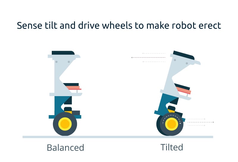
The segway tries to get the angle down to 0°. If the angle is positive, the segway brakes or accelerates backwards. If it's negative the segway accelerates forward.
But which signal get the motors? This is exactly the task of the pid-Controller.
The proportional-part: The angle should be 0°. So the greater the angle, the higher the speed of the motors.
Mathematically you can write:
angle_error = angle_should - angle_is
p-Motor-value = k_p * angle_error
The integral-part: When the current angle isn't zero, the Controller tries to get the segway horizontally again. But this approach shouldn't be slow and the smaller the angle-values, the slower the changes. Therefore the Controller allows a faster approach with the disadvantage, that the movement doesn't stop at 0° and goes a bit to the other side. This behaviour is guaranteed by the integral-part. All the angles are added (integrated) and this integral over time should be Zero. So if the angle is f.e. positive for a while, the Controller tries to get the seqway into the negative area. This guaranteeds faster approaches...
Mathematically you can write:
error_sum_new = error_sum_old + error
i-motor-value = k_i * (error_sum_new)
error_sum_old = error_sum_new
The derivative-part: Not just the current angle is important but also the changes of the angle. Let me explain: If the angle is f.e. 10° and it doesn't Change a lot, the Motors don't need to correct this shift very fast. But if the angle is 10° and it changes very fast (high derivative), than the motors have to correct this also very fast.
Mathematically you can write:
d-motor-value = k_d * angular Speed
Finally you get: motor-value = p-motor-value + i-motor-value + d-motor-value

Step 4: The Complete Setup

Picture of The Complete Setup
3 More Images
Now it's time to start the segway. To drive not only straight ahead you have to mount two buttons. When you push f.e. the right one, the left Motor increases Speed and the right Motor slows down. To ensure smooth transitions the added and deducted value starts at zero and increases step by step (+0.5 every loop) until he reaches the maximum value (f.e. 30).
To try out your own segway I 've attached the simple program for you. Good luck and don't follow the segway-inventor James Heselden down a cliff ;-)
Maybe you want to take a look at my YouTube-channel: www.youtube.com/user/stopperl16/Videos
// -------------------------------------------------------------------------------------------------------------------------------------------------------------------------
// ------------  Programm zur Berechnung des Neigungswinkels aus den Gyro- und Beschleunigungsdaten unter Verwendung eines Kalman-Filters ----------------------------------
// --------------------------  und PID-Regelung zur seriellen Ansteuerung der beiden Motoren mittels Sabertooth-Motortreiber -----------------------------------------------
// -------------------------------------------------------------------------------------------------------------------------------------------------------------------------


#include "Wire.h"
#include "I2Cdev.h"      // I2Cdev and MPU6050 must be installed as libraries
#include "MPU6050.h"     // class default I2C address is 0x68 = AD0 low
#include <math.h>
#include <SoftwareSerial.h>
#include <SabertoothSimplified.h>

SoftwareSerial SWSerial(NOT_A_PIN, 11);          // RX on no pin (unused), TX on pin 11 (to S1).
SabertoothSimplified ST(SWSerial);               // Use SWSerial as the serial port.

MPU6050 accelgyro;

int16_t ax, ay, az;   // Beschleunigungswerte in x-,y- und z-Richtung des MPU6050-Sensors
int16_t gx, gy, gz;   // Winkelgeschwindigkeitswerte in x-,y- und z-Richtung des MPU6050-Sensors

#define Pin_Lenkung_rechts      12               // Pin-Anschluss für den Lenkbefehl Rechts
#define Pin_Lenkung_links       13               // Pin-Anschluss für den Lenkbefehl Links

#define Pin_Schalter_Box        3                // Pin-Anschluss des Box-Schalters, um zwischen Motorsynchronisation und I-Regelung zu wählen

#define Pin_PID_Regelung_P      A1               // Pin-Anschluss für das Poti zur Veränderung des P-Anteils
#define Pin_PID_Regelung_I      A2               // Pin-Anschluss für das Poti zur Veränderung des I-Anteils
#define Pin_PID_Regelung_D      A3               // Pin-Anschluss für das Poti zur Veränderung des D-Anteils


int LoopTime_Soll = 9;                           // gewünschte Schleifendauer in ms um auf die 100 Hz zu gelangen      
int LoopTime_Angepasst = LoopTime_Soll;          // letzte Schleifenzeit mit erzwungener Pause
int LoopTime_Bisher = LoopTime_Soll;             // letzte Schleifenzeit ohne erzwungener Pause
unsigned long LoopTime_Start = 0; // Startzeit der Schleife

float Winkel; // aktueller Neigungswinkel
float Winkel_Soll;                               // Sollwert des Neigungswinkels, also 0°
float Winkel_Grenze;                             // maximal erlaubter Neigungswinkel, über dem das Segway abgeschaltet wird   

float ACC_angle; // Winkel vom Beschleunigungssensor
float GYRO_rate;                  // Winkelgeschwindigkeit vom Gyro-Sensor

float Kp,Ki,Kd,K;                                // Konstanten zur PID-Regelung, Differentteil, Integralteil, Differentialteil, Gesamtanteil
int Motor;                                       // von der PID-Regelung erhaltener Wert zur Motoransteuerung
int Motor_rechts, Motor_links;                   // Werte für die beiden Motoren
float K_Motor_links, K_Motor_rechts;             // Korrekturfaktoren für einen synchronen Lauf der beiden Motoren

int Schalter_Box;                                // Variable, welche die Schalterstellung an der Box abfragt

int Lenkung_Eingang_rechts = 0;                  // Variable zum Erfassen eines Lenkbefehls nach Rechts
int Lenkung_Eingang_links = 0;                   // Variable zum Erfassen eines Lenkbefehls nach Links
float Lenkung_max;                               // Wert, um den sich die Motoransteuerung bei einem Lenkbefehl maximal ändern soll
float Lenkung_rechts, Lenkung_links;             // aktueller und schrittweise erhöhter Ansteuerungswert beim Lenken nach rechts bzw. links


// ****************************************************************************
// ****************************** SETUP ***************************************
// ****************************************************************************


void setup()
   {
    Wire.begin(); 
     
    //SWSerial.begin(9600);     // This is the baud rate you chose with the DIP switches.
     
    Serial.begin(9600);    // baud rate für den seriellen Monitor, um die Werte zu überprüfen
    
    // initialize device
    accelgyro.initialize();
            
    calibrateSensors();       // Unterprogramm zum einmaligen Kalibrieren der Sensoren
   }


// ***********************************************************************************
// ****************************** Kalibrierung ***************************************
// ***********************************************************************************


void calibrateSensors()              // einmalige Ermittlung der Sensor-Nullwerte (Mittelwert aus jeweils 50 Messungen)
   {
    
    // =================================================
    // ======== Änderung der Sensor-Auflösung ==========
    // =================================================
    
    // ===========================================================================
    // read raw accel/gyro measurements from device
    // Ausgabewerte-Acc: Auflösung 2g:  16384/g    Auflösung 4g:  8192/g
    // Ausgabewerte-Gyro: Auflösung 250°/s:  131/°/s   Auflösung 500°/s:  65.5/°/s
    // ===========================================================================
    
    accelgyro.setFullScaleAccelRange(MPU6050_ACCEL_FS_2);
    accelgyro.setFullScaleGyroRange(MPU6050_GYRO_FS_500);


    // Versuch, das "Aufheulen" der beiden Motoren zu Beginn zu vermeiden
    
    ST.motor(1, 0);
    ST.motor(2, 0);


    Winkel_Soll = 0.0;                 // Sollwert für den Neigungswinkel
    Winkel_Grenze = 30.0;              // maximal erlaubter Neigungswinkel
    
    
    // *******************************************************
    // ********** K - Werte für die PID-Regelung *************
    // *******************************************************
    
    
    Kp = analogRead(Pin_PID_Regelung_P) * 25.0 / 1023.0;        // Differenzenanteil mit Poti festgelegt
    Ki = 0.1;                                                   // Integralanteil mit Poti festgelegt (Schalter aber womöglich auf Motorkorrektur, daher mit 0.1 zunächst festgesetzt)   
    Kd = analogRead(Pin_PID_Regelung_D) * 100.0 / 1023.0;       // Differentialanteil mit Poti festgelegt
    K = 1.0;                                                    // Gesamtanteil


    // **************************************************
    // ********** K - Werte für die Motoren *************
    // **************************************************


    pinMode(Pin_Schalter_Box, INPUT);      // Pin für die Auswahl zwischen I-Regelung und Motorsynchronisation
    
    K_Motor_rechts = 1.0;                  // Korrekturfaktor für den rechten Motor
    K_Motor_links = 0.8;                   // Korrekturfaktor für den linken Motor
      
    
    // **********************************************
    // ********** Werte für die Lenkung *************
    // **********************************************
    
    
    Lenkung_max = 25.0;                      // Wert, um den sich die Motoransteuerung bei einem Lenkbefehl MAXIMAL ändern soll
    Lenkung_rechts = 0.0;                    // aktueller Zusatzwert beim Lenkvorgang nach rechts
    Lenkung_links = 0.0;                     // aktueller Zusatzwert beim Lenkvorgang nach links

    pinMode(Pin_Lenkung_rechts, INPUT);      // Pin für Lenkung nach Rechts wird als Input deklariert
    pinMode(Pin_Lenkung_links, INPUT);       // Pin für Lenkung nach Links wird als Input deklariert
      
   }


// ***************************************************************************************************************************************************
// ***************************************************************************************************************************************************
// ********************************************************************** HAUPTSCHLEIFE **************************************************************
// ***************************************************************************************************************************************************
// ***************************************************************************************************************************************************

void loop()
   {

   // *******************************************************
   // ********************* Sensorabfrage *******************
   // *******************************************************
   
    // ===========================================================================
    // read raw accel/gyro measurements from device
    // Ausgabewerte-Acc: Auflösung 2g:  16384/g    Auflösung 4g:  8192/g
    // Ausgabewerte-Gyro: Auflösung 250°/s:  131/°/s   Auflösung 500°/s:  65.5/°/s
    // ===========================================================================
    
    accelgyro.getMotion6(&ax, &ay, &az, &gx, &gy, &gz);
   
    ACC_angle = atan(ay * 1.0 / az * 1.0) * 180.0 / 3.141592654;       // Auflösung 2g:  16384/g
   
    //ACC_angle = atan((ay/16384.0) / (az/16384.0)) * 180.0 / 3.141592654;       // Auflösung 2g:  16384/g
    
    GYRO_rate = gx/65.5;                                 // Auflösung 500°/s:  65.5/°/s


   // *******************************************************
   // ********** K - Werte für die PID-Regelung *************
   // *******************************************************
    
    
    Kp = analogRead(Pin_PID_Regelung_P) * 25.0 / 1023.0;                     // Differenzenanteil mit Poti festgelegt; Maximum = 25
    Kd = analogRead(Pin_PID_Regelung_D) * 100.0 / 1023.0;                    // Differentialanteil mit Poti festgelegt; Maximum = 100

    Schalter_Box = digitalRead(Pin_Schalter_Box);                            // Abfrage des Pins für den Schalterzustand an der Box
    
    if (Schalter_Box == HIGH)                                                // Mittels Schalter an der Box I-Regelung aktiviert
       {
        Ki = analogRead(Pin_PID_Regelung_I) * 2.0 / 1023.0;                  // Integralanteil mit Poti festgelegt; Maximum = 2        
       }
    else                                                                     // Mittels Schalter an der Box Motor-Regelung aktiviert
        {
         K_Motor_rechts = analogRead(Pin_PID_Regelung_I) * 2.0 / 1023.0;     // Korrekturfaktor für einen synchronen Lauf der beiden Motoren; Maximum = 2
        }


     // ********************************************************************************
     // ****************** Kalmanfilter, PWM-Berechnung und Motorwerte *****************
     // ********************************************************************************
     
     
     Winkel = kalmanCalculate(ACC_angle, GYRO_rate, LoopTime_Angepasst); // mit Kalmanfilter berechneter Winkel

     
     if (Winkel > Winkel_Grenze || Winkel < (Winkel_Grenze * (-1)))
        {
         // ===============================================
         // Abbruch aufgrund des zu großen Neigungswinkels!
         // ===============================================
         
         ST.motor(1, 0);
         ST.motor(2, 0);
        }
     else
        {
         // =========================
         // Neigungswinkel in Ordnung
         // =========================
      

         Motor = pid(Winkel, Winkel_Soll, GYRO_rate);      // Berechnung des PWM-Werts zur Ansteuerung der Motoren 
     
         Motor_rechts = K_Motor_rechts * Motor;            // Berechnung der mittels K-Faktor synchronisierten Motordrehzahl für den rechten Motor

         Motor_links = K_Motor_links * Motor;              // Berechnung der mittels K-Faktor synchronisierten Motordrehzahl für den linken Motor


         // **************************************************************************************
         // ***** Abfrage ob die Lenkung betätigt wurde und Veränderung der Motoransteuerung *****
         // **************************************************************************************
     
     
         Lenkung_Eingang_rechts = digitalRead(Pin_Lenkung_rechts);   // Abfrage des Pins für Lenkung nach Rechts

         if (Lenkung_Eingang_rechts == HIGH)
            {     
              // ******************************************
              // *** Lenkung nach Rechts wurde gedrückt ***
              // ******************************************
          
              if (Motor_rechts >= 0)    // segway fährt gerade vorwärts oder steht. Welcher Motor abgefragt wird, ist egal.
                 {
                  Motor_rechts = Motor_rechts - (int)Lenkung_rechts;   // Vielleicht auch mit Multiplikation eines Faktors (z.B. * (1 - 0.1) versuchen
                  Motor_links = Motor_links + (int)Lenkung_rechts;     // Vielleicht auch mit Multiplikation eines Faktors (z.B. * (1 + 0.1)) versuchen
                 }
              else                      // segway fährt gerade rückwärts
                 {
                  Motor_rechts = Motor_rechts + (int)Lenkung_rechts;   // Vielleicht auch mit Multiplikation eines Faktors (z.B. * (1 + 0.1) versuchen
                  Motor_links = Motor_links - (int)Lenkung_rechts;     // Vielleicht auch mit Multiplikation eines Faktors (z.B. * (1 - 0.1) versuchen
                 }
                 
             Lenkung_rechts = Lenkung_rechts + 0.05;                                 // Besser nur um z.B. 0.1 pro Abfrage erhöhen, damit Lenkung nicht zu abrupt erfolgt!
             
             if (Lenkung_rechts > Lenkung_max) Lenkung_rechts = Lenkung_max;        // Maximaler Lenkungswert darf nicht überschritten werden!
             
             //Lenkung_rechts = constrain(Lenkung_rechts, 0, Lenkung_max);          // rechter Lenkungswert ins Intervall [0,Lenkung_max] gebracht
            } 
         else
            {
             Lenkung_rechts = 0.0;
            }
    
    
         Lenkung_Eingang_links = digitalRead(Pin_Lenkung_links);    // Abfrage des Pins für Lenkung nach Links

         if (Lenkung_Eingang_links == HIGH)
            {     
              // *****************************************
              // *** Lenkung nach Links wurde gedrückt ***
              // *****************************************
          
              if (Motor_links >= 0)    // segway fährt gerade vorwärts oder steht. Welcher Motor abgefragt wird ist egal.
                 {
                  Motor_rechts = Motor_rechts + (int)Lenkung_links;   // Vielleicht auch mit Multiplikation eines Faktors (z.B. * (1 + 0.1) versuchen
                  Motor_links = Motor_links - (int)Lenkung_links;     // Vielleicht auch mit Multiplikation eines Faktors (z.B. * (1 - 0.1) versuchen
                 }
              else                      // segway fährt gerade rückwärts
                 {
                  Motor_rechts = Motor_rechts - (int)Lenkung_links;   // Vielleicht auch mit Multiplikation eines Faktors (z.B. * (1 - 0.1) versuchen
                  Motor_links = Motor_links + (int)Lenkung_links;     // Vielleicht auch mit Multiplikation eines Faktors (z.B. * (1 + 0.1) versuchen
                 }
                 
             Lenkung_links = Lenkung_links + 0.05;                                 // Besser nur um z.B. 0.1 pro Abfrage erhöhen, damit Lenkung nicht zu abrupt erfolgt!
             
             if (Lenkung_links > Lenkung_max) Lenkung_links = Lenkung_max;        // Maximaler Lenkungswert darf nicht überschritten werden!
             
             //Lenkung_links = constrain(Lenkung_links, 0, Lenkung_max);          // linker Lenkungswert ins Intervall [0,Lenkung_max] gebracht
            } 
         else
            {
             Lenkung_links = 0.0;
            }


         // *******************************************************************************************
         // ******************************** Ansteuern der Motoren  ***********************************
         // *******************************************************************************************
        
         
         Motor_rechts = constrain(Motor_rechts, -127, 127);          // rechter Motorenwert ins Intervall [-127,127] gebracht
         Motor_links = constrain(Motor_links, -127, 127);            // linker Motorenwert ins Intervall [-127,127] gebracht
         
                      
     /*
         // Gebrauch einer Wurzelfunktion anstelle der linearen Ansteuerfunktion zur Verbesserung des Ansprechverhaltens bei niedrigen Motorwerten
         // ======================================================================================================================================
         
         if (Motor_rechts >= 0)     // rechter Motor dreht vorwärts
            { 
             Motor_rechts = sqrt(127 * Motor_rechts);             // zur Verbesserung des Ansprechverhaltens bei niedrigen Motorwerten
              
             ST.motor(2, Motor_rechts);      
            }
         else                       // rechter Motor dreht rückwärts
            {
             Motor_rechts = -sqrt(127 * -Motor_rechts);           // zur Verbesserung des Ansprechverhaltens bei niedrigen Motorwerten
             
             ST.motor(2, Motor_rechts);               
            }


         if (Motor_links >= 0)      // linker Motor dreht vorwärts
            {
             Motor_links = sqrt(127 * Motor_links);               // zur Verbesserung des Ansprechverhaltens bei niedrigen Motorwerten 
             
             ST.motor(1, Motor_links);               
            }
         else                       // linker Motor dreht rückwärts
            {
             Motor_links = -sqrt(127 * -Motor_links);             // zur Verbesserung des Ansprechverhaltens bei niedrigen Motorwerten 
             
             ST.motor(1, Motor_links);  
            }
         */
         
         ST.motor(1, Motor_links);
         ST.motor(2, Motor_rechts);
         
        } 


   // ************************************************************************ 
   // *********************** Ausgabe der Messwerte **************************
   // ************************************************************************

    Werteausgabe();


   // ******************************************************************
   // *********************** Tastaturabfrage **************************
   // ******************************************************************

   // Tastatureingabe();


   // **********************************************************************
   // *********************** loop timing control **************************
   // **********************************************************************

     LoopTime_Bisher = millis() - LoopTime_Start;        // Zeit seit der letzten Schleife
     
     if(LoopTime_Bisher < LoopTime_Soll)
        {
         delay(LoopTime_Soll - LoopTime_Bisher);         // Verzögerung, um die gleiche Schleifenzeit zu erhalten
        }
     
     LoopTime_Angepasst = millis() - LoopTime_Start;     // aktualisierte Dauer der letzten Schleife, sollte gleich LoopTime_Soll = z.B. 10 msek sein!
     LoopTime_Start = millis();                          // neue Starteit der Schleife
   
 }


// ********************************************************************************************
// ****************** Werteausgabe an die serielle Schnittstelle ******************************
// ********************************************************************************************

void Werteausgabe()
   {
    /*
    Serial.print(Winkel);
    Serial.print("     ");
    Serial.println(Motor);
    Serial.print("     ");
    */
    
    Serial.print("a_y = ");
    Serial.print(ay/16384.0);
    Serial.print("    a_z = ");
    Serial.print(az/16384.0);
    Serial.print("    ACC_angle = ");
    Serial.print(ACC_angle,0);
    Serial.print("    GYRO_rate = ");
    Serial.print(GYRO_rate,0);
    Serial.print("    Winkel: ");
    Serial.println(Winkel,0);
    
    /*
    Serial.print("   Motor: ");
    Serial.print(Motor);
    Serial.print("    Motor_rechts: ");
    Serial.print(Motor_rechts);
    Serial.print("    Motor_links: ");
    Serial.println(Motor_links);
    */
    
   }


// ******************************************************************************************************
// ***************************************** PID-Steuerung **********************************************
// ******************************************************************************************************

float error;
float last_error = 0;
float pTerm;
float iTerm;
float dTerm;
float integrated_error = 0;
int GUARD_GAIN = 40;           // maximal aufintegrierter Winkelfehler

   int pid(float Winkel_aktuell, float Winkel_Vorgabe, float Winkelgeschwindigkeit)
      {
       error = Winkel_Vorgabe - Winkel_aktuell;
       
       pTerm = Kp * error;                                                         // Differenzenanteil
       
       
       integrated_error = integrated_error + error;
   
       iTerm = Ki * constrain(integrated_error, -GUARD_GAIN, GUARD_GAIN);          // Integralanteil
  
       
       dTerm = Kd * Winkelgeschwindigkeit / 100.0;                                 // Differentialanteil; :100 um auf brauchbare Werte zu kommen!
       
       /*
       Serial.print("    K_p: ");
       Serial.print(pTerm);
       Serial.print("    K_d: ");
       Serial.println(dTerm);
       */
  
       last_error = error;
  
       // Serial.println(K*(pTerm + iTerm + dTerm));
       
  
       return constrain(K*(pTerm + iTerm + dTerm), -127, 127);                     // Ausgabe des Motorwerts für die beiden Motoren innerhalb der Grenzen [-127,127]
      } 


// ******************************************************************************************************
// ************************************** Kalman filter module ******************************************
// ******************************************************************************************************


    float Q_angle  =  0.001; // E(alpha2) = 0.001
    float Q_gyro   =  0.003;  // E(bias2) = 0.003
    float R_angle  =  0.001;  // Sz = 0.03   !!! je größer die Zahl, desto unempfindlicher reagiert der Winkel auf Veränderungen !!!
    float x_angle = 0;
    float x_bias = 0;
    float P_00 = 0, P_01 = 0, P_10 = 0, P_11 = 0;
    float dt, y, S;
    float K_0, K_1;

  float kalmanCalculate(float newAngle, float newRate, int looptime)
     {
      dt = float(looptime)/1000;    // dt in Sekunden
      x_angle = x_angle + dt * (newRate - x_bias);
      P_00 = P_00 - dt * (P_10 + P_01) + Q_angle * dt;
      P_01 = P_01 - dt * P_11;
      P_10 = P_10 - dt * P_11;
      P_11 = P_11 + Q_gyro * dt;

      y = newAngle - x_angle;
      S = P_00 + R_angle;
      K_0 = P_00 / S;
      K_1 = P_10 / S;

      x_angle +=  K_0 * y;
      x_bias  +=  K_1 * y;
      P_00 -= K_0 * P_00;
      P_01 -= K_0 * P_01;
      P_10 -= K_1 * P_00;
      P_11 -= K_1 * P_01;

      return x_angle;
     }


// ********************************************************************
// ******** Tastaturabfrage zur Veränderung der PUI-Parameter *********
// ********************************************************************

int Tastatureingabe()
   {
    if(!Serial.available())    return 0;
   
    char param = Serial.read();                            // get parameter byte
  
    if(!Serial.available())    return 0;
  
    char cmd = Serial.read();                              // get command byte
  
    Serial.flush();
  
    switch (param)
       {
        case 'p':
           if(cmd=='+')    Kp++;
           if(cmd=='-')    Kp--;
           break;
        case 'i':
           if(cmd=='+')    Ki += 0.1;
           if(cmd=='-')    Ki -= 0.1;
           break;
        case 'd':
           if(cmd=='+')    Kd++;
           if(cmd=='-')    Kd--;
           break;
       case 'k':
           if(cmd=='+')    K += 0.2;
           if(cmd=='-')    K -= 0.2;
           break;
       case 'l':
           if(cmd=='+')    K_Motor_links += 0.1;
           if(cmd=='-')    K_Motor_links -= 0.1;
           break;
       case 'r':
           if(cmd=='+')    K_Motor_rechts += 0.1;
           if(cmd=='-')    K_Motor_rechts -= 0.1;
           break;
     
       default:
           Serial.print("?");           Serial.print(param);
           Serial.print(" ?");          Serial.println(cmd);
      }
  
    Serial.println();
    Serial.print("K:");                      Serial.print(K);
    Serial.print("   Kp:");                  Serial.print(Kp);
    Serial.print("   Ki:");                  Serial.print(Ki);
    Serial.print("   Kd:");                  Serial.print(Kd);
    Serial.print("   K_Motor_links:");       Serial.print(K_Motor_links);
    Serial.print("   K_Motor_rechts:");      Serial.println(K_Motor_rechts);
   } 

สรุปงานที่ 5 Internet of Things (IoT)

Internet of Things (IoT) คืออะไร           Internet of Things (IoT) คือ  "อินเตอร์เน็ตในทุกสิ่ง" หมายถึง การที่อุปกรณ์ต่างๆ ส...